Think of every possible testbench situation as a cell in a grid. If we work one example per cell, the reader is covered everywhere. Here is the grid for this topic.
#
Case class
What makes it tricky
Covered by
C1
Combinational DUT, exhaustive
no clock, must let output settle
Ex 1
C2
Sequential DUT, one edge
must sample after the edge
Ex 2
C3
Sequential DUT, full sweep
counter wraps around (limiting value)
Ex 3
C4
Degenerate input: reset / all-zero
flip-flops start as x (unknown)
Ex 4
C5
Sign / two's-complement edge
overflow at the sign boundary
Ex 5
C6
Timing: clock period ↔ frequency
unit conversion, the 2d trap
Ex 6
C7
Race at the exact edge
old vs new value coexist (delta cycles)
Ex 7
C8
Blocking vs non-blocking swap
= vs <= give different results
Ex 8
C9
Real-world word problem
"how long will this sim take?"
Ex 9
C10
High-Z + exam twist: != vs !== with x/z
unknowns silently pass a bad check
Ex 10
Every row below is tagged with the cell it fills. Together they touch every cell.
Several examples below hinge on how a Verilog simulator orders events inside a single instant of time. Rather than gloss it, here is the concrete rule.
Keep this box in mind; every "delta cycle" reference below points back to it.
Forecast: guess — how many input rows, and what is y for a=1,b=1?
Count the input space. Two 1-bit inputs → 22=4 combinations.
Why this step? Exhaustive testing is only sane when the input count is small; 4 is cheap, so we test all of them (no case escapes).
Enumerate. Drive {a,b} = binary 0,1,2,3:
a
b
y=a⊕b
0
0
0
0
1
1
1
0
1
1
1
0
Why this step? XOR means "different → 1, same → 0". This is the golden reference the TB compares to.
Count delay waits. The loop runs once per row, each with one #10. So 4 waits ×10=40 time units total.
Why this step? For a combinational DUT there is no clock — we insert a delay so the output can settle before we read it.
Verify (concrete): the simulator would print no $error lines and end with a single XOR OK message. The self-check numbers: the y column contains exactly two1s (rows 01, 10), and the loop consumes 4×10=40 time units. Both are machine-checked below.
Forecast: does q become 1at the edge, or just after?
State the flip-flop rule. On each rising clock edge, q copies d.
Why this step? This is the whole behaviour — the DUT has no other logic.
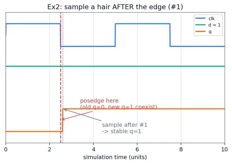
Look at the instant of the edge.(Figure s01: three stacked waveforms — blue clk, green d=1, orange q. The red dashed line marks the rising edge where old q=0 and new q=1 momentarily coexist; the gray dotted line just after it shows the #1 sample point where q has stably become 1.) At the edge, the oldq=0 and the newq=1 both exist — the new value is still sitting in the NBA region (see the delta-cycle box above) and has not been committed.
Why this step? A non-blocking <= computes its result in the active region but writes it only in the later NBA region, so an on-edge read may catch the stale value.
Sample after #1.@(posedge clk); #1; read q; reads the committedq=1.
Why this step? The #1 advances simulation time past all delta cycles at the edge, so the NBA write is done — a race-free read.
Verify (concrete): a simulator sampling with #1 prints q=1, matching d=1; sampling on the edge might print q=0 (see the waveform figure s01). The committed value q=1 is checked below.
Forecast: a 4-bit register — what is its largest value, and what happens when you add 1 to it?
Range of a 4-bit register. 4 bits store 0 to 24−1=15.
Why this step? The limiting value (the top of the range) is where wrap-around bugs live.
Count 15 edges. Starting at 0, after 15 increments q=15 (binary 1111).
Why this step? Straightforward accumulation before the interesting event.
The 16th edge — wrap.15+1=16, but only 4 bits are kept: 16mod16=0. So after 16 edges q=0 again.
Why this step? Hardware silently drops the carry-out; the modulo captures that. Your TB's expected must also wrap, or it will falsely flag an error.
The 17th edge.q=1.
Why this step? Confirms the counter resumes normally past the wrap.
Verify (concrete): the printed sequence would be 0,1,2,...,15,0,1. Specifically after 16 edges q=0; after 17 edges q=1; top value =15. All checked below.
Forecast:x means "I don't know". What is "unknown +1"?
Meaning of x.x means the simulator cannot decide the bit's value.
Why this step? Un-reset flip-flops power up as x — this is the degenerate, all-unknown case.
Propagate through +1. Any arithmetic with an x bit yields x: x + 1 = x.
Why this step? Unknown poisons everything downstream; the counter stays x forever.
Consequence. Every self-check q !== expected fires (or, worse, silently passes when written with != — see Ex 10). The run tells you nothing.
Why this step? This is why the parent note says always assert reset first.
Verify (concrete): the waveform would show q = xxxx for all cycles (never a clean number). We can't put a literal x into ordinary integer arithmetic, so the check below models the rule "unknown-plus-one is still unknown" as a small function add1('x') == 'x', and confirms it never collapses to a definite number.
Forecast: what is "one more than the most positive number" in fixed-width signed hardware?
Two's-complement range for 4 bits. With 4 bits, signed values run −23=−8 up to 23−1=+7.
Why this step? The sign boundary+7→−8 is the classic overflow edge — a case class of its own.
Raw bits of +7.+7 = 0111. Add 1 → 1000.
Why this step? We track the literal bits because hardware only knows bits, not signs.
Reinterpret 1000 as signed. In two's complement, 1000=−8.
Why this step? The top bit is the sign; 1000 decodes to −8, so +7+1 "wraps" to −8. A TB comparing against a signed golden model must expect −8, not +8.
One toggle is only half a period. The clock is low for d then high for d, so a full cycle is T=2d.
Why this step? The single commonest timing mistake is forgetting the factor of 2 — see the parent's clock derivation. Note d is just the delay after the #.
Plug in d=3 ns.T=2×3=6 ns.
Why this step? Direct substitution.
Frequency is the reciprocal.f=1/T=1/(6 ns)=1/(6×10−9s)≈166.67 MHz.
Why this step? Frequency answers "how many cycles per second" — the inverse of "seconds per cycle".
Solve for the target 250 MHz.T=1/f=1/(250×106)=4 ns, so d=T/2=2 ns.
Why this step? Invert the whole chain: pick f, get T, halve for d.
(Figure s02: a blue square-wave clk. An orange double-arrow spans one half-period labelled d = 3 ns; a green double-arrow spans the full cycle labelled T = 2d = 6 ns with the resulting frequency. It makes the 2d relationship literally visible: the toggle delay is only half the period.)
Verify (concrete): with #3 the printed period between two rising edges is 6 ns → f≈166.67 MHz; to hit 250 MHz you code #2. T=6 ns, f≈166.67 MHz, d=2 ns — all checked numerically below.
Forecast: at the edge, is q the old 4 or the new 5?
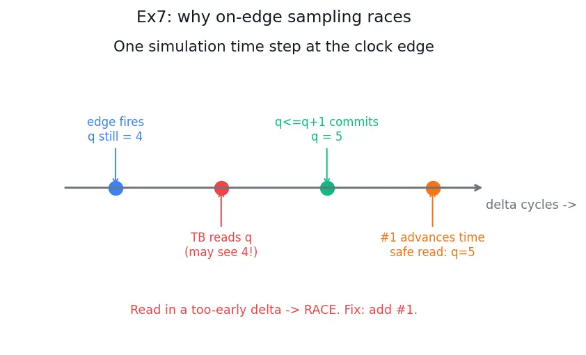
Order of events at one time-step.(Figure s03: a horizontal "delta cycles →" timeline through one clock instant, with four coloured dots in order: (1) edge fires, q still 4; (2) TB reads q — may still see 4; (3) q<=q+1 commits in the NBA region, q becomes 5; (4) #1 advances time, safe read gives 5. It shows the read landing before the commit — the race.) At the edge, both the DUT's always and the TB's @(posedge) wake up in the same time step, but the non-blocking update commits in the later NBA region (see the delta-cycle box).
Why this step? Delta cycles are zero-time sub-steps; the read may happen in the delta before the write commits.
Read window. If the TB reads in the pre-update delta, q is still 4 → the q==5 test fails spuriously.
Why this step? This is a race: the outcome depends on scheduler ordering, not on your design.
The fix. Insert #1 (advance real sim time) so all deltas at the edge finish first. Now q=5 is committed.
Why this step? Advancing time guarantees the NBA write is done before you sample.
Verify (concrete): with #1 the print shows q=5; the committed post-edge value =5 is checked below.
Blocking = runs top-to-bottom, immediately.a = b sets a=0now; then b = a sees the newa=0, so b=0.
Result: (a,b)=(0,0).
Why this step? Blocking updates take effect before the next line executes — so the second line uses the just-changed value.
Non-blocking <= samples RHS first, updates at end of delta. Both right-hand sides are read (in the active region) with the old values (a=1,b=0), then applied together in the NBA region: a←0, b←1.
Result: (a,b)=(0,1) — a clean swap.
Why this step? This deferred update (delta-cycle box) is exactly why flip-flops in real designs use <= (see Blocking vs Non-blocking Assignments).
Testbench lesson. For DUT sequential logic use <=; for TB stimulus use = so inputs change immediately at a chosen time.
Why this step? Mixing them is the trap the parent note warns about.
Verify (concrete): simulator prints A: a=0 b=0 and B: a=0 b=1. Both checked below.
Cycles counted. 1 reset cycle + 20 test cycles = 21 cycles.
Why this step? We must include the reset cycle — it also waits for a posedge.
Time per cycle. Period T=2×5=10 ns (from always #5).
Why this step? Reuse the T=2d rule from Ex 6.
Total.21×10=210 ns of simulated time.
Why this step? Multiply cycles by seconds-per-cycle to get total elapsed virtual time.
Sanity on the meaning. This 210 ns is simulated time (what $time reports at $finish), not how long your CPU spends running the sim — that wall-clock runtime depends on your machine and can be far shorter or longer (parent note: sim time ≠ real time).
Why this step? Beginners conflate the two; making the distinction explicit prevents "why did my 210 ns sim take 3 seconds?" confusion.
Answer: the stimulus block consumes 210 ns of simulated time.
Verify (concrete):$time at $finish reads 210 (plus the tiny #1 nudges we ignored). 21×10=210 ns checked below.
Forecast: does a bad (unknown or floating) output get caught, or does it slip through silently?
Evaluate q != 3 when q = xxxx. Because q has x bits, != returns x (unknown), not 1.
Why this step?!= is blind to x; it cannot commit to "not equal", so it hands back x.
How if treats that x. An if condition treats x (and 0 and z) as false.
Why this step? This is the silent killer: if (x) does not run the body, so $error never fires — a broken DUT passes.
Evaluate q !== 3 when q = xxxx.!== compares bit-for-bit: xxxx versus 0011 clearly differ (the x bits are not 0/1), so it returns a firm 1 (true). The $errorfires — bug caught.
Why this step?!== never returns x; it always gives 0/1, so it never goes blind.
Now the floating case q = zzzz (high-Z). Same logic: q != 3 returns x → treated false → misses the floating bug. q !== 3 sees the z bits differ from 0011 → returns 1 → catches it.
Why this step? A floating output is often worse than a wrong one (it can read as random on real silicon), so you absolutely need !== to catch it. This is the high-impedance edge case the matrix demanded.
Verify (concrete): for q = xxxx: !== vs 3 is true (fires), != is unknown → if treats false (does not fire). For q = zzzz: identical outcome — !== fires, != slips. All four outcomes checked below.
#1 after @(posedge clk) before checking?
To advance past the delta cycles at the edge so the NBA (non-blocking) write has committed, avoiding a race. ::: Sample a hair after the edge so the non-blocking update has landed.
Recall 4-bit counter: value after 16 edges from 0?
16mod16=0 — it wraps back to 0. ::: 0
Recall Signed 4-bit:
+7+1=?
Bits 0111→1000 = −8. ::: −8
Recall
always #d clk = ~clk; gives what period and frequency?
T=2d, f=1/(2d). ::: Period is twice the toggle delay d.
Recall Why
!== and not != in a self-check, and what are the four logic values?
The values are 0,1,x (unknown),z (high-Z). != returns x on any x/z input, which if treats as false → bug slips through; !== compares bit-for-bit and returns a firm 1/0, catching x/z. ::: The triple/two-bang exact operator sees unknowns and floating.
Back to Testbenches and simulation · deeper on unknowns and coverage: Functional Coverage and Verification, SystemVerilog Assertions (SVA).