Every timer problem is one (or a blend) of these cells. Each worked example below is tagged with the cell(s) it covers.
| # |
Cell (case class) |
What makes it tricky |
Example |
| A |
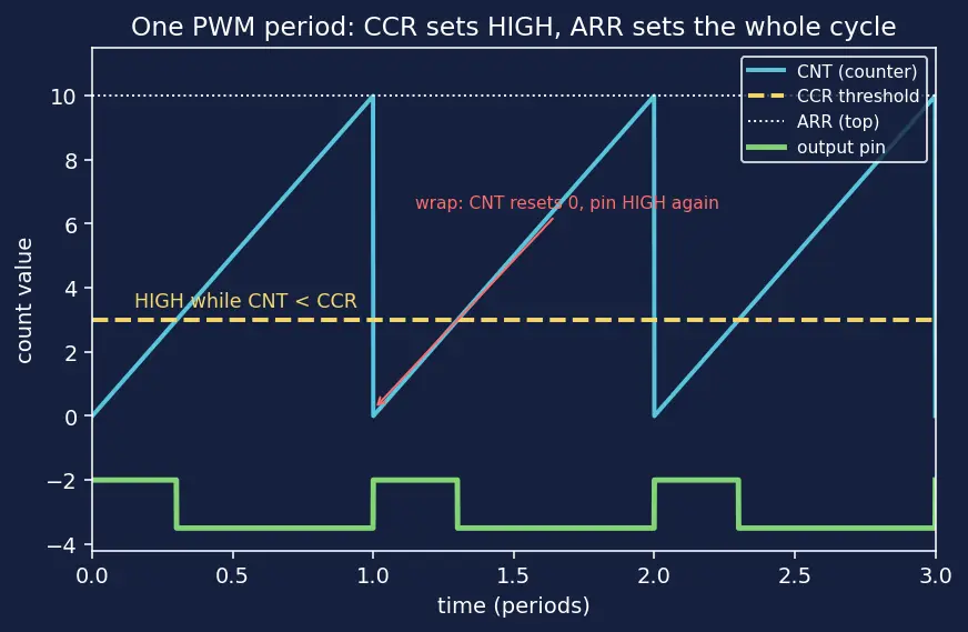
Forward design, PWM % — pick PSC/ARR/CCR for a target frequency + duty |
choosing PSC to keep ticks tidy |
Ex 1 |
| B |
Forward design, pulse-width (servo/ESC) — set CCR in µs, not % |
duty is irrelevant; width matters |
Ex 2 |
| C |
Degenerate duty — 0%, 100%, and the off-by-one at the top |
CCR=ARR+1 vs CCR=ARR |
Ex 3 |
| D |
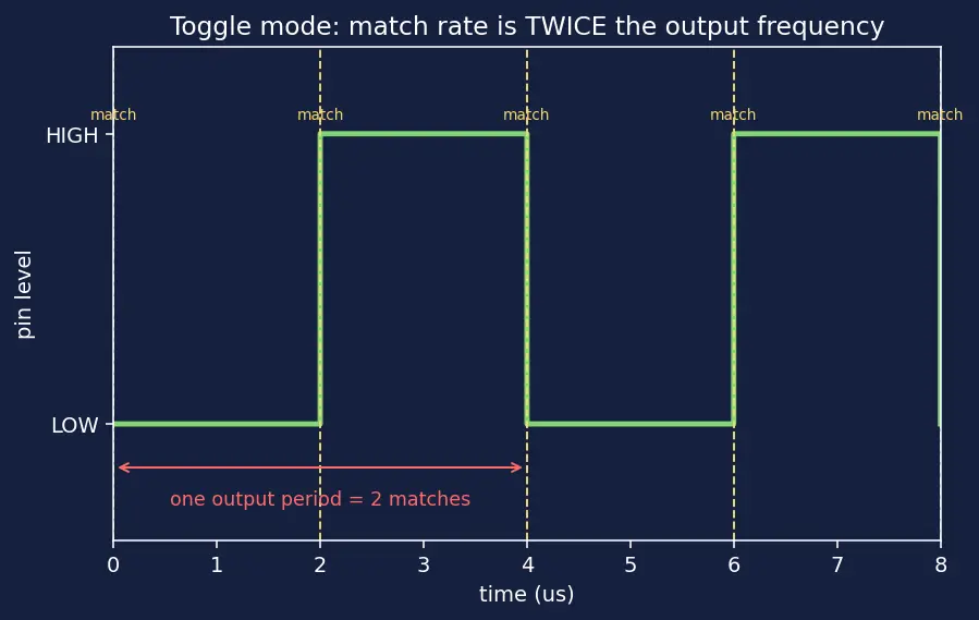
Toggle mode — square wave, divide-by-2 subtlety |
two toggles = one period |
Ex 4 |
| E |
Input capture, no wrap — measure a frequency |
plain subtraction |
Ex 5 |
| F |
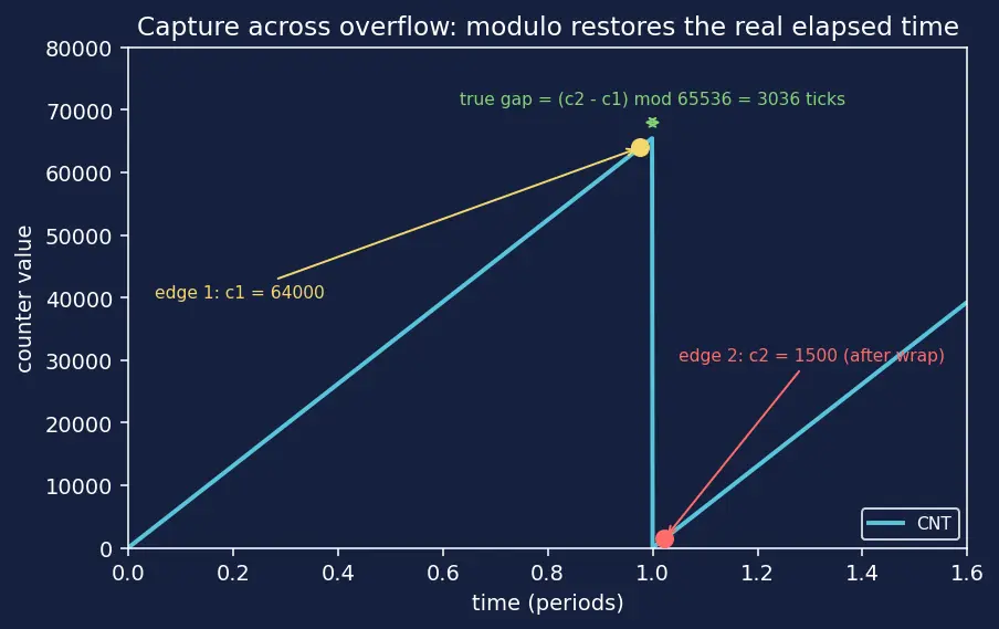
Input capture, WITH wrap — the negative-difference trap |
modulo arithmetic |
Ex 6 |
| G |
Limiting / resolution — smallest & largest frequency a 16-bit timer can hit |
ARR range limits |
Ex 7 |
| H |
Real-world word problem — dim an LED to a perceived brightness |
mapping physical want → registers |
Ex 8 |
| I |
Exam twist — given a scope reading, reverse-engineer the registers |
invert every formula |
Ex 9 |
- Parent topic (Hinglish) — the machinery these examples exercise.
- Clock Tree and Prescalers — where fclk and the tidy-tick choices come from.
- GPIO and Alternate Functions — the pin every PWM/toggle example drives.
- Interrupts and NVIC — overflow-counting for the Cell F wrap case.
- Servo and ESC Control — Example 2's pulse-width interpretation.
- Motor Control and H-Bridges — Example 1 & 8 style duty control at speed.
- Encoder Mode — a capture cousin for the curious.


